Section 2. The Rotating Housing (Bezel)
The rotating housing, often called the bezel, is the circular ring that rotates through 360° around the compass. It contains the degree scale, orienting lines, orienting arrow and declination scale used for setting and measuring bearings.
Unlike the base plate, which always remains stationary, the bezel is designed to turn independently. Every time you take a bearing, plot a bearing on your map or orientate your map to the landscape, you will rotate the bezel to align these features correctly.
One of the most important things to understand is that everything inside the bezel moves together as a single unit. When you rotate the bezel, the degree markings, orienting lines, orienting arrow and declination scale all rotate together. Only the magnetic needle continues to point towards magnetic north.
Throughout the Stirling Ridge Walk you'll constantly adjust the rotating housing as you navigate between features such as Pyungoorup Peak, Baker's Knob, Isongerup Peak and Ellen Peak. Learning to rotate the housing confidently is one of the fundamental skills of compass navigation.
Rotating components shown
• Rotating housing (bezel)
• Bearing Numbers (range 0°–360°)
• Cardinal directions (N,S,E and W)
• Orienting arrow ("The Shed")
• Orienting lines (meridian)
• Declination scale (range 0°– 80°)
• West declination (WDECL)
• East declination (EDECL)
Rotating Housing (Bezel)Deep Dive
The rotating housing, often called the bezel, is the circular component that surrounds the magnetic needle. Unlike the base plate, which always remains fixed in your hand, the bezel rotates through a full 360° and allows the compass to be set for a specific direction.
Many people assume the bezel is simply a ring with numbers printed around it. In reality, it is one of the most important parts of the compass because it provides the reference system used for almost every navigation task. Whether you are taking a bearing from the landscape, plotting a bearing onto your map, following a course through the bush or performing a resection, the bezel is continually being adjusted intentionally.
The Degree Scale
Around the outside of the bezel is a degree scale ranging from 0° to 360°.
North is marked as 0° (or 360°).
East is 90°.
South is 180°.
West is 270°.
These numbers represent directions rather than distances. A bearing of 75° points in a very different direction from a bearing of 105°, even though they differ by only 30°.
On most quality compasses each small division represents 2 degrees, allowing surprisingly accurate navigation when used correctly. For demonstration purpose the divisions used in the diagrams on this website are in 1 degree.
Why the Bezel Rotates
Imagine you are standing on the saddle between Ellen Peak and Pyungoorup Peak, looking west towards Pyungoorup.
The photograph shows two stages of taking a bearing.
In the first stage on left, the compass is pointing towards Pyungoorup Peak, but the bezel has not yet been set. The red end of the magnetic needle is pointing north, as it always does, but the orienting arrow inside the bezel is not aligned with it. At this stage, you are not yet ready to take an accurate bearing.
In the second stage on right, the compass baseplate itself has not moved. The direction of travel arrow and the bearing at Index Marker remain pointing towards Pyungoorup Peak. Only the bezel has been rotated. It has been turned until the orienting arrow, or “the shed,” aligns with the red end of the magnetic needle. This is “Red in the Shed.”
This is an important distinction. Rotating the bezel does not change the direction in which the compass needle is pointing. The direction of travel arrow and the index marker are fixed parts of the baseplate and do not rotate with the bezel. They remain aimed towards Pyungoorup Peak while the bezel rotates independently.
Once Red is in the Shed, the bearing can be read where the degree scale on the rotating bezel meets the fixed Index Marker. In this example, the reading is 270°, which is due west towards Pyungoorup Peak.
Notice also that the magnetic needle has not been rotated to obtain the bearing. It continues to point towards Magnetic North throughout the process. What you rotate is the bezel, bringing its orienting arrow into alignment with the magnetic needle while keeping the direction of travel arrow pointed towards your target.
That is why the bezel rotates: the magnetic needle provides the reference to Magnetic North, while the rotating bezel allows you to measure and retain the direction of travel as a bearing.
Orienting Lines
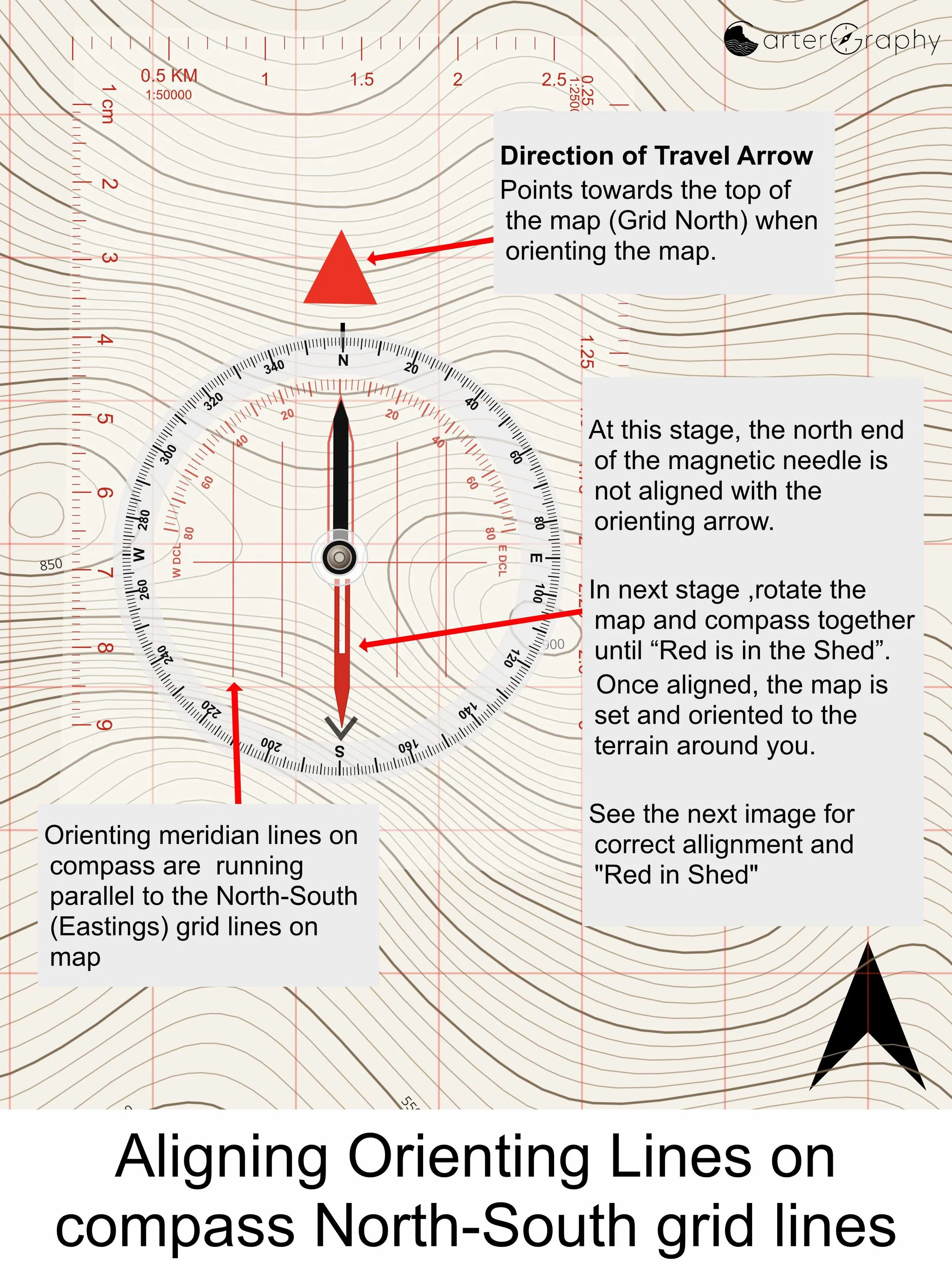
Inside the rotating housing are a series of parallel orienting lines. In the images below, these can be seen as the parallel red lines running through the compass housing.
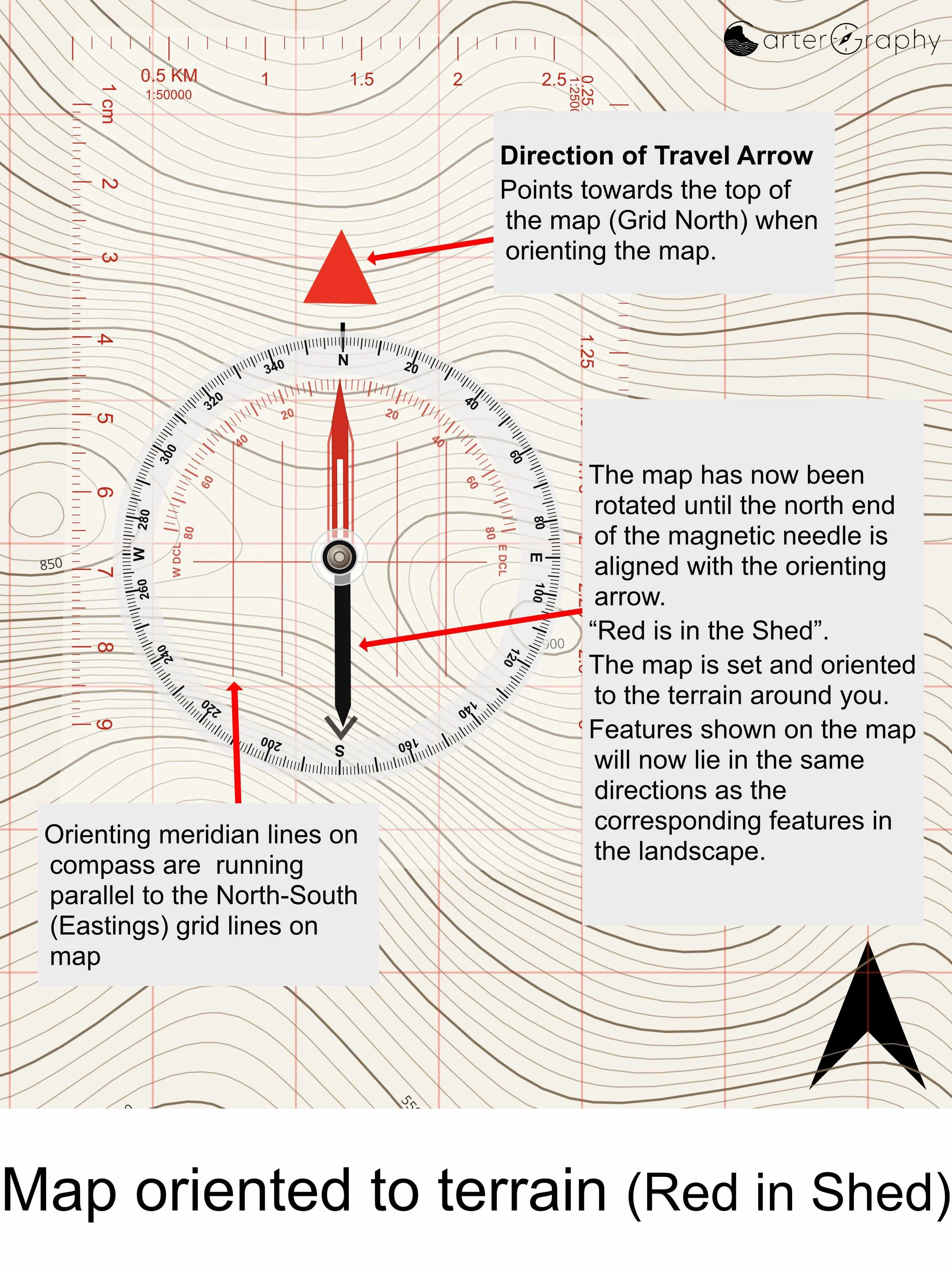
When working with a topographic map, these orienting lines are aligned parallel with the north–south Easting grid lines on the map, as shown in the images. This provides a clear visual reference between the compass and the map, ensuring future bearings will be accurate.
The orienting lines are fundamental to using a baseplate compass on a map. By keeping them parallel with the map's north–south grid lines, you can accurately take a bearing from the map or plot a bearing back onto it from a bearing taken in the field.
The Direction of Travel Arrow
The Direction of Travel Arrow, shown on the baseplate in the images, is fixed in position and does not rotate with the bezel.
When orienting a map, the arrow provides an important reference for placing the compass correctly. Position the compass on the map with the Direction of Travel Arrow pointing towards the top of the map, towards Grid North. The orienting lines inside the rotating housing can then be aligned parallel with the map's north–south Easting grid lines.
In the first image, the magnetic needle is not yet “Red in the Shed.” This is deliberate for demonstration purposes. It shows the compass positioned correctly on the map before the map has been oriented.
In the second image, the map and compass have been rotated together, without changing their position relative to each other, until the red magnetic needle aligns with the orienting arrow. No magnetic declination has been considered.
Once “Red is in the Shed”, the map is oriented and the features shown on the map correspond directionally with the surrounding terrain.
Magnetic Declination
Many modern compasses include a declination scale within the rotating housing.
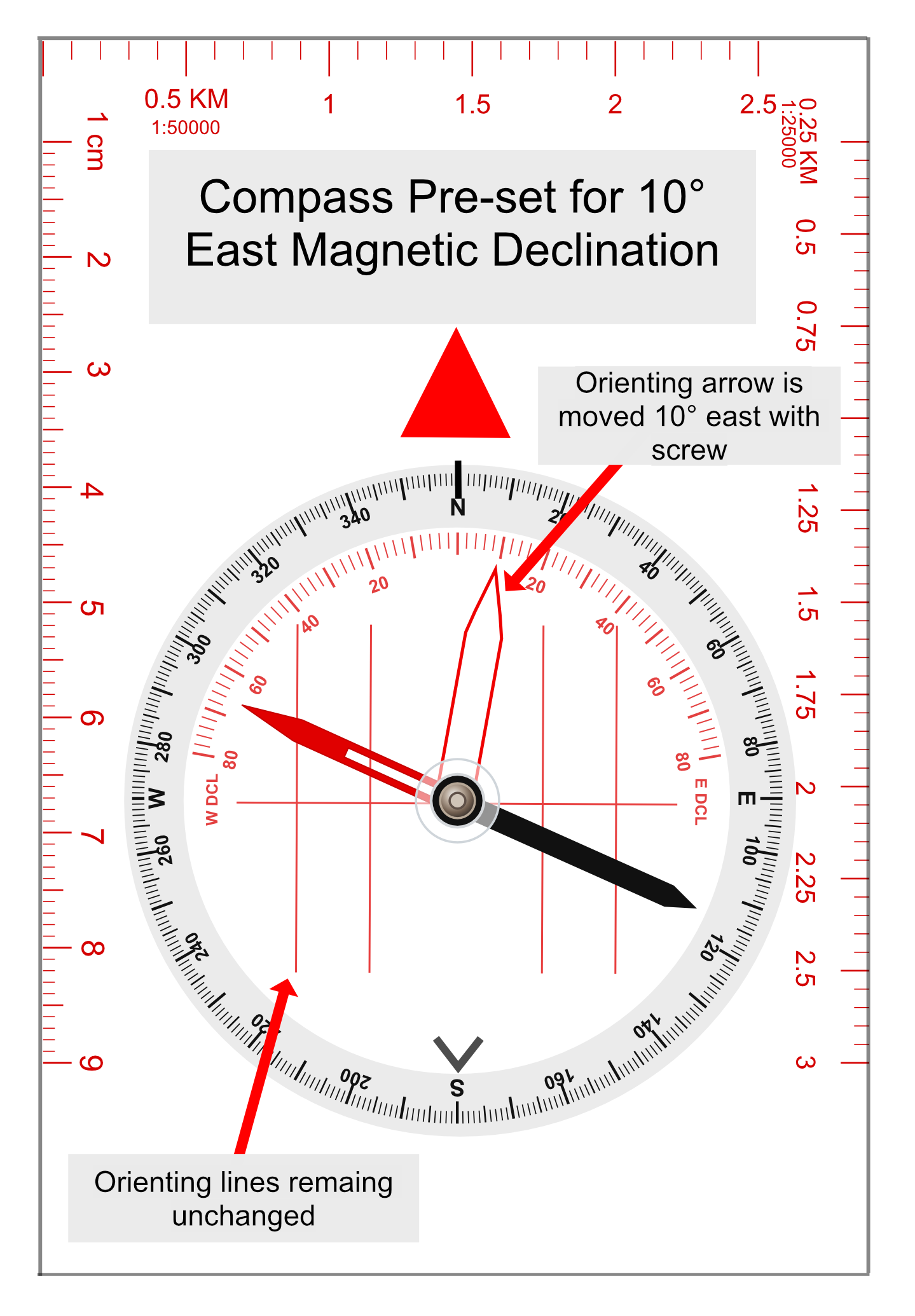
On compasses with adjustable declination, a small adjustment screw allows the orienting arrow to be moved independently of the orienting lines. This is an important distinction. The orienting lines remain fixed within the housing and are aligned with the north–south grid lines on the map, while the orienting arrow can be offset to account for the difference between Grid North and Magnetic North.
Once the local declination has been set using the adjustment screw, the orienting arrow is therefore not necessarily parallel with the orienting lines.
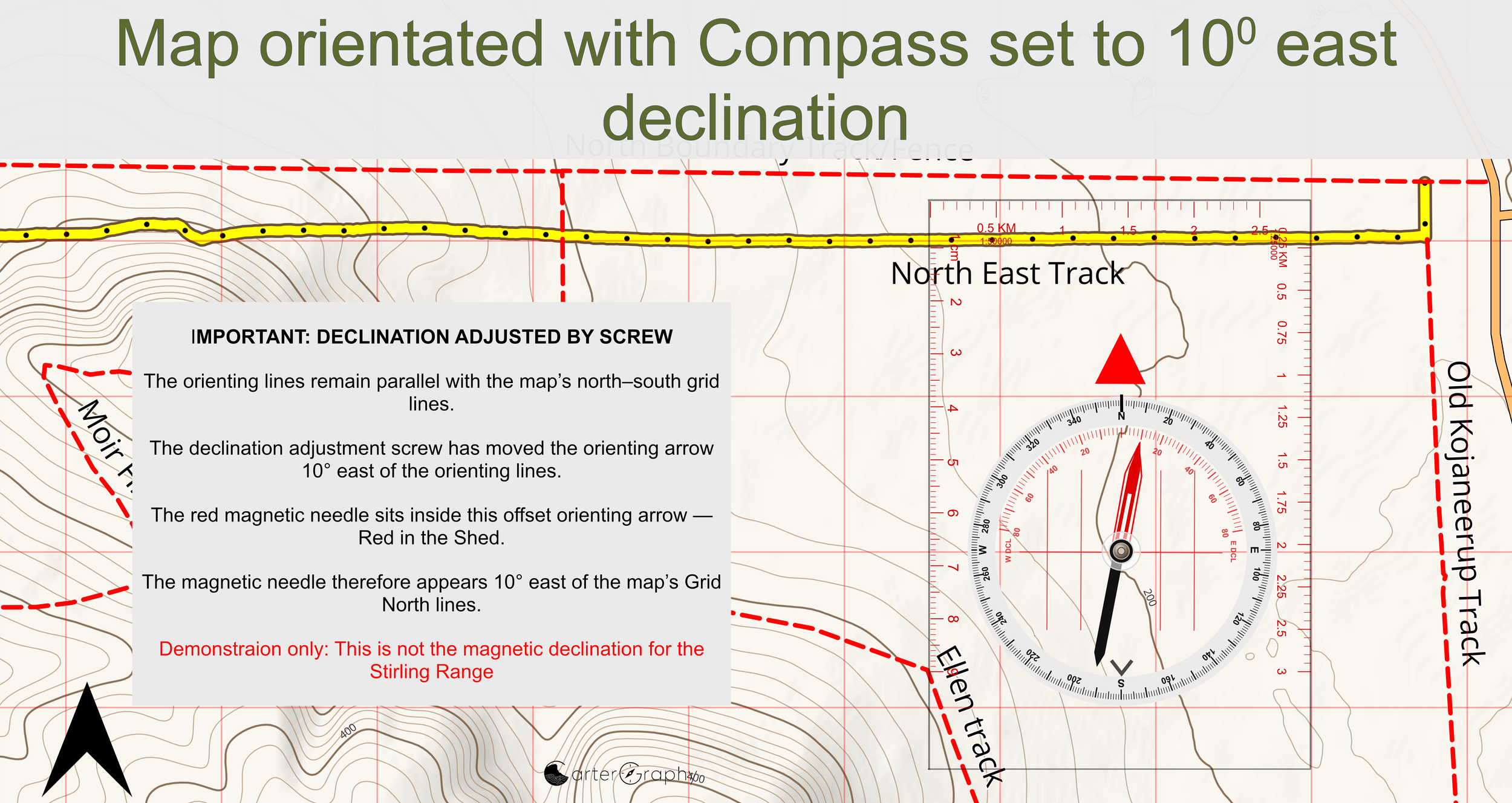
The two diagrams below demonstrate this using an exaggerated magnetic declination of 10° east. In the first diagram, the declination adjustment screw has moved the orienting arrow 10° east while the orienting lines remain unchanged. The angle between the orienting lines and the orienting arrow represents the magnetic declination that has now been adjusted into the compass.
In the second diagram, the compass is placed on the map with the orienting lines parallel to the map’s north–south grid lines. The map and compass are then rotated together until the red end of the magnetic needle sits inside the offset orienting arrow — Red in the Shed. Because the orienting arrow has already been adjusted 10° east, the magnetic needle will now visibly point approximately 10° east of the map’s Grid North lines. This is correct and does not mean that the map needs to be rotated further.
The orienting lines remain referenced to Grid North. The orienting arrow is offset to account for Magnetic North.
Once declination has been correctly adjusted into the compass, you do not need to calculate and apply the correction manually each time you transfer a bearing between the map and compass. The adjustment is incorporated into the relationship between the orienting arrow and orienting lines.
For the Stirling Range, magnetic declination is relatively small, but I prefer to account for it even when the difference is only around one degree. If you are taking a bearing, there is little reason not to make it as accurate as reasonably possible. A one-degree error may appear insignificant on the compass, but that small angular difference becomes increasingly important as the distance travelled or plotted increases.
For that reason, throughout this guide I apply the local magnetic declination rather than simply ignoring it. Later sections will demonstrate just how much difference a one-degree error can make over distance, particularly when plotting bearings, following a bearing or carrying out a resection.
Note: The 10° east declination shown in these diagrams is deliberately exaggerated for demonstration purposes. It is not the magnetic declination for the Stirling Range.
A Common Beginner Error
One of the most common errors is rotating the bezel accidentally while walking.
If the bezel moves by even a few degrees without you noticing, every subsequent bearing will be incorrect. This is why experienced navigators develop the habit of glancing at the bezel regularly to confirm that the correct bearing is still set.
Many quality compasses use positive clicks as the bezel rotates. These clicks help prevent accidental movement while still allowing precise adjustments.
Key Points
The rotating housing (bezel)is much more than a ring of numbers. It is the adjustable reference system that allows your compass to store a direction independently of the magnetic needle. By combining the degree scale, orienting lines and orienting arrow, the bezel enables you to transfer bearings accurately between your map and the terrain, making it one of the most important components of the entire compass.